
Tall Form Spray Dryer
28 มีนาคม 2566
ผู้ชม 418 ผู้ชม
SUMMARY
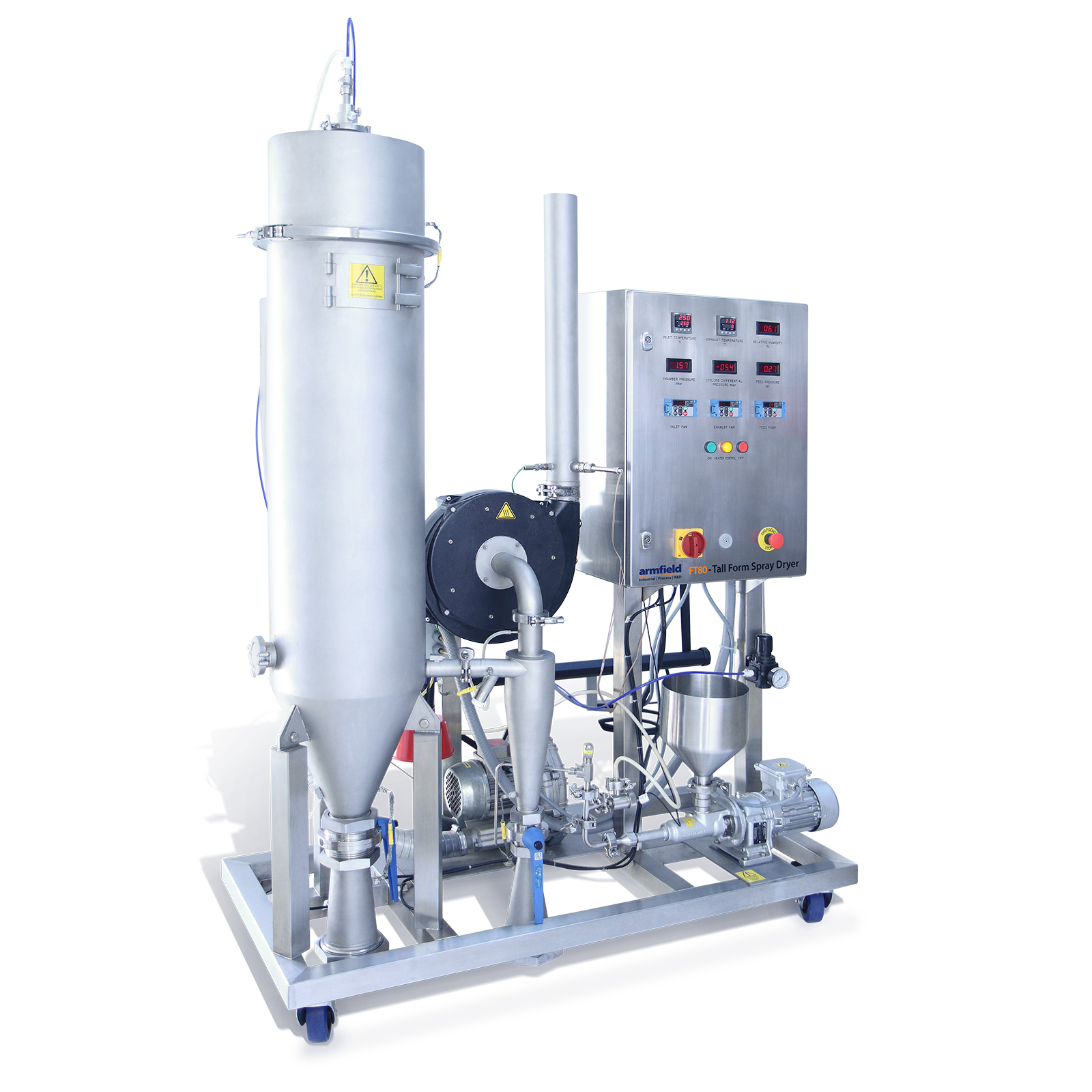
The Armfield FT80 Tall Form Spray Dryer and FT81 Tall Form Spray Chiller have been purpose designed to enable laboratory quantities of products to be processed.
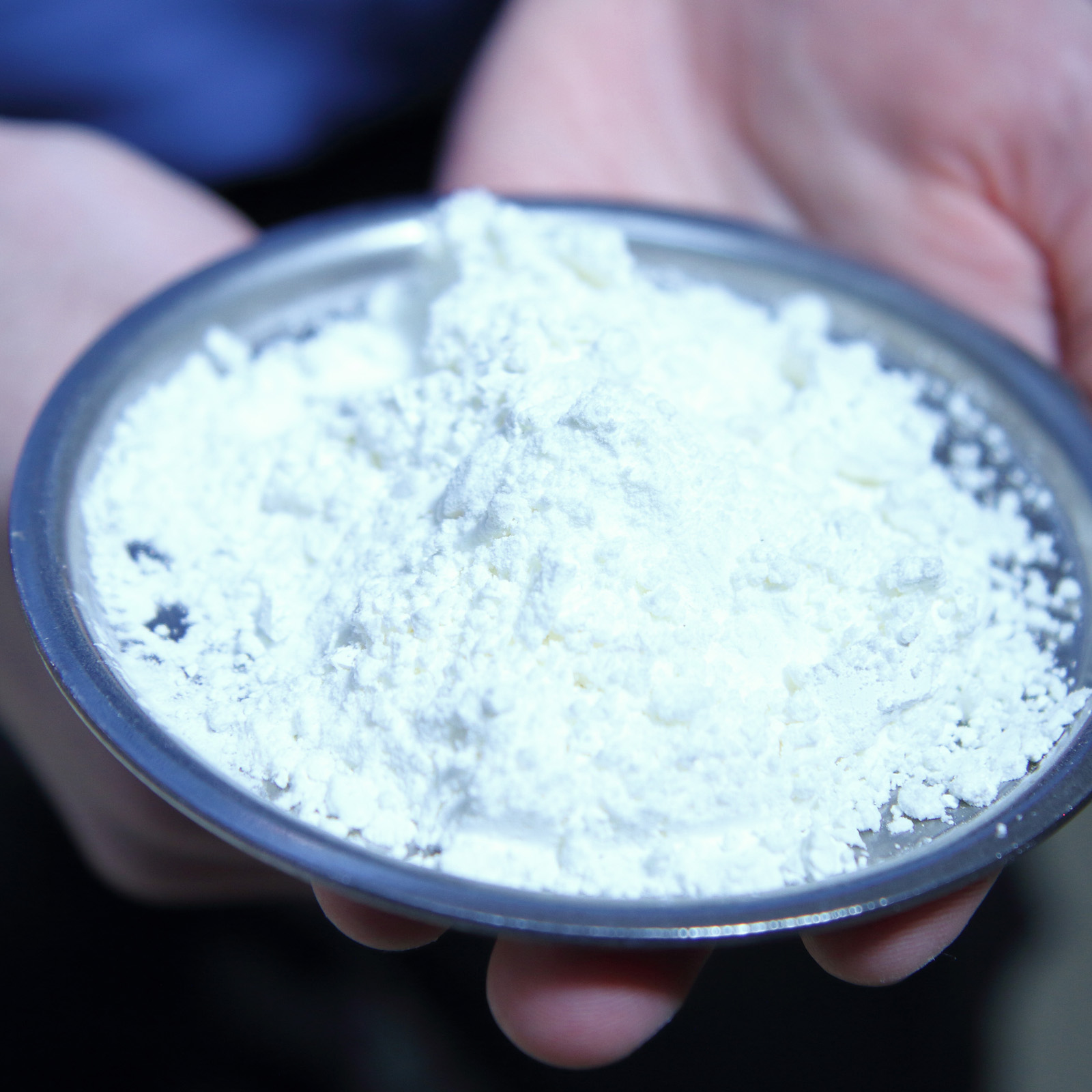
Despite the size of the equipment, the powders produced will be comparable to large-scale production dryer capability. Both systems offer unparalleled flexibility with separate, individually controlled inlet and outlet fans, together with variable nozzle positions and selection of co- or counter-current flow configurations.
This flexibility is enhanced by an unsurpassed range of options, purpose-designed for laboratory and research use. With the appropriate accessories it is possible to change from spray-drying to spray-chilling configurations in a matter of minutes, thus adding further unique experimental capability.
Configurations
CO-CURRENT SPRAY-DRYING CONFIGURATION
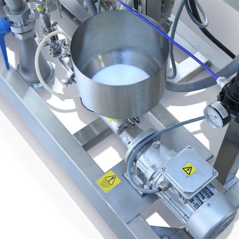
The liquid to be dried is pumped to the top of the drying chamber by a variable-speed progressing cavity pump, which provides a very smooth flow and constant flow rate.
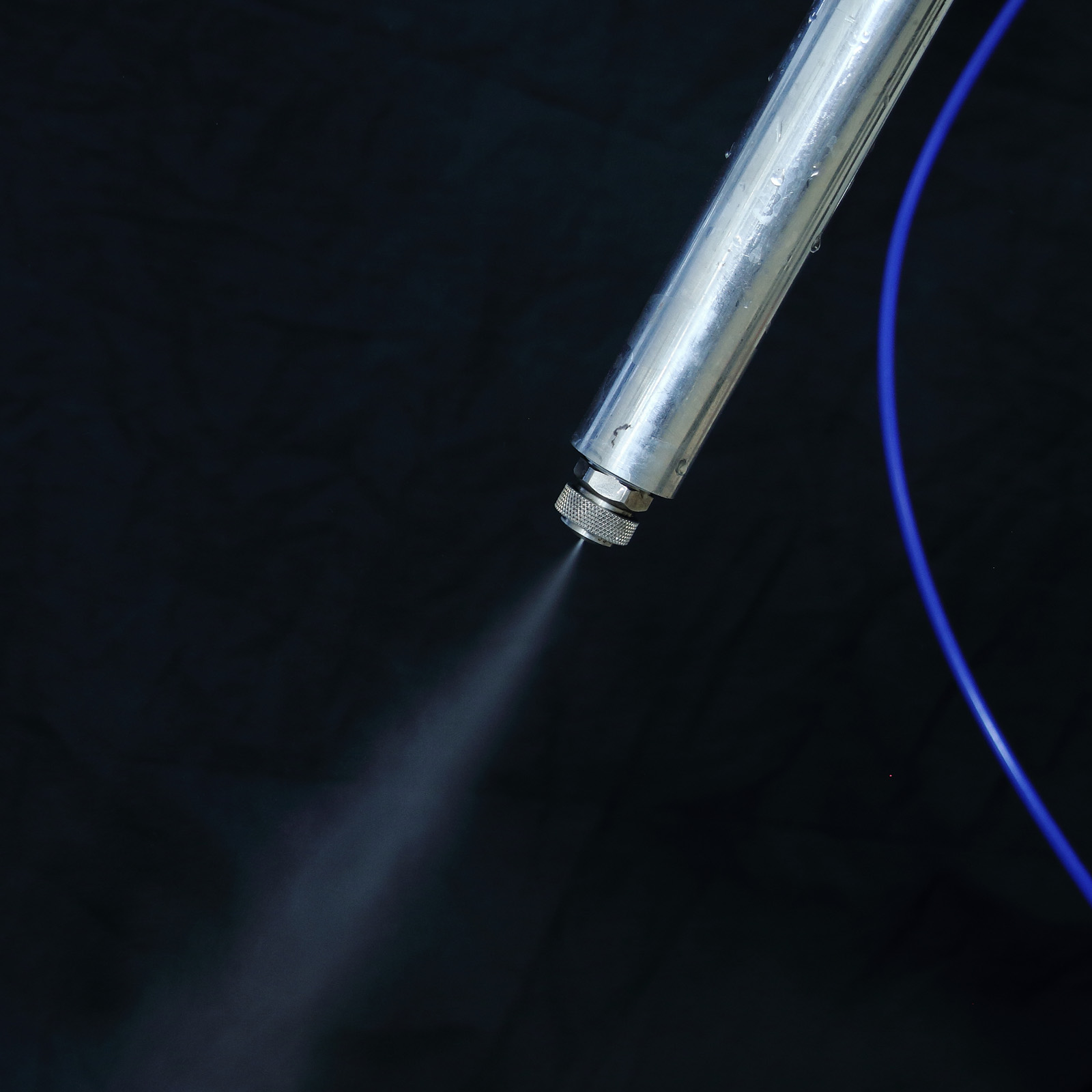
It is atomised by a two-fluid nozzle and enters the drying chamber as a fine droplet dispersion. Hot air is blown into the chamber, on to the droplets causing flash evaporation of the surface moisture. The bound moisture in the particles is evaporated in the time that they fall to the discharge point at the base of the cone (the residence time). In this configuration the particle temperature will never exceed the wet bulb temperature of the exhaust air.
A variable-speed centrifugal fan provides control over the inlet air flow and a steady inlet temperature is achieved by using a three-term controller in conjunction with an electric heater. A second variable speed fan draws air from the chamber through a cyclone separator. This ‘push-pull’ fan system provides flexibility to operate the chamber at variable pressures with variable residence times. Two powder collection points are provided, one at the bottom of the main chamber, and one on the cyclone separator. This enables particles of different sizes to be collected simultaneously and/or separately.
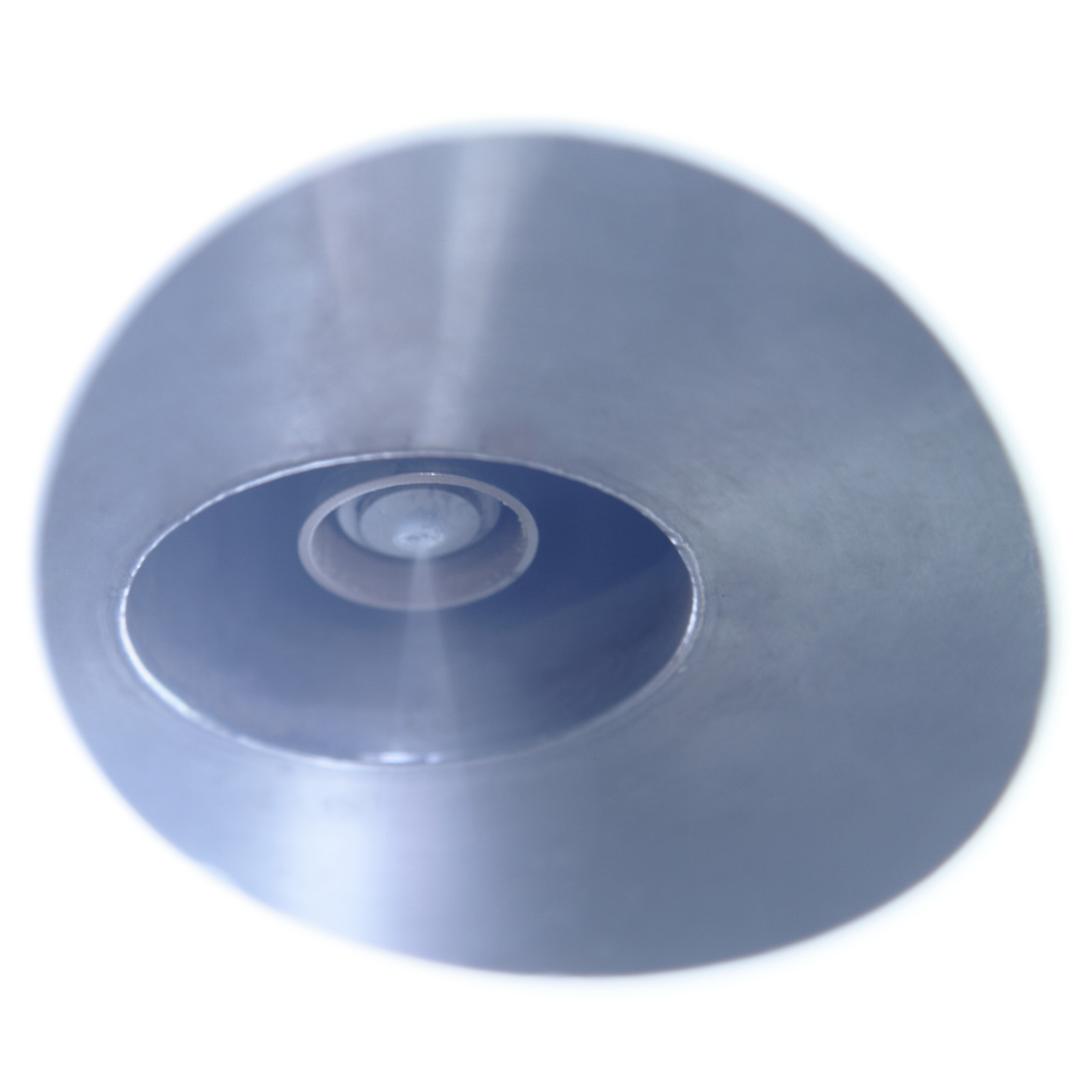
Exhaust-air relative humidity can be measured and controlled so as to enable the system to run at the required RH level. The nozzle is an external-mix two-fluid atomising nozzle. Compressed air is directed onto the liquid stream as it leaves the nozzle body and immediately atomises it. With this type of nozzle the orifice is larger than a single fluid type, and so it is possible to atomise more viscous products and even products containing suspended solids.
COUNTER-CURRENT SPRAY-DRYING CONFIGURATION
The FT80 Tall Form Spray Dryer is supplied as standard with two nozzles and nozzle hoses, one for co-current and one for counter-current. In counter-current configuration the nozzle is positioned at the bottom of the chamber and sprayed upward into the flow of hot air.
FT81 PROCESS LINE
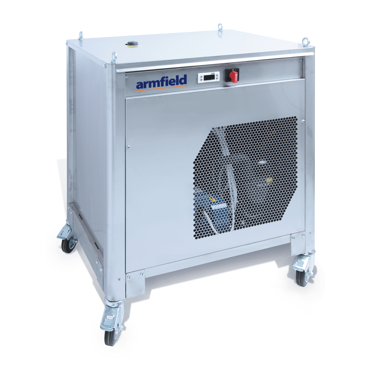
FT81 Tall Form Spray chiller operates in conjunction with FT63 laboratory chiller. This unit uses counter current spray to chill the liquid particles for an extended residence time.
Armfield-FT63 Chiller
SPRAY CHILLER CONFIGURATION
For spray chilling the flow of air from the inlet fan to the spray chamber is chilled instead of heated. The air is cooled using chilled water and a stainless steel heat exchanger.
The FT81 Tall Form Spray Chiller is supplied complete with its own refrigeration unit. Counter-current configuration is normally used for spray chilling. Note: Many spray-chilling applications also require the Trace Heating Accessory, FT81-65.
The FT80-60 Fluid Bed Cooler AccessorySoftware
WINDOWS™ DATA LOGGING SYSTEMS
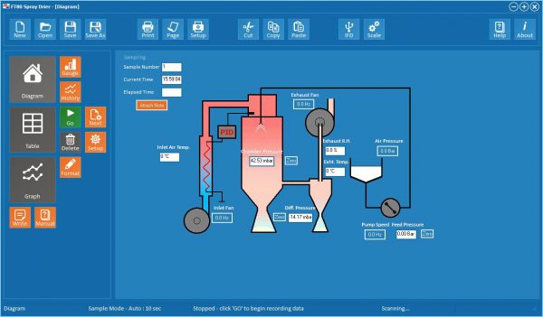
A unique benefit of the Armfield miniature-scale food processing range is that the measured data may be captured and stored to disk. An Armfield FT80-DTA-ALITE Data Logging Accessory transfers results to a PC. Temperatures, pressures and relative humidity can be monitored in real-time.
The data can be displayed in graphical and tabular forms and printed. A PC with a USB port, and running Windows XP or later is required.
ARMSOFT
The armSOFT software enables the operator to select the appropriate stage of the process and a mimic diagram with measured variables is displayed. The speed of the pump can be varied to meet the required flow rate.
Results are saved in a log, which can be viewed and manipulated with the armBUS results viewer. Results can be printed or exported in a spreadsheet format, which can be opened in a wide range of packages for further analysis.
- No clogging, no need for de-blocking devices
- Co-current flow for drying heat sensitive products
- Counter-current flow maximises chamber residence time for non-heat sensitive products
- Relative humidity displayed
- Residence times in the drying cylinder variable up to 9 seconds
- Easy connections to electrical and compressed air utilities
- Data recording to computer for rapid evaluation and comparison
- Accessory sets are available to quickly change from drying to spray chilling
- Available as a Spray Dryer (FT80) or as a Spray Chiller (FT81)
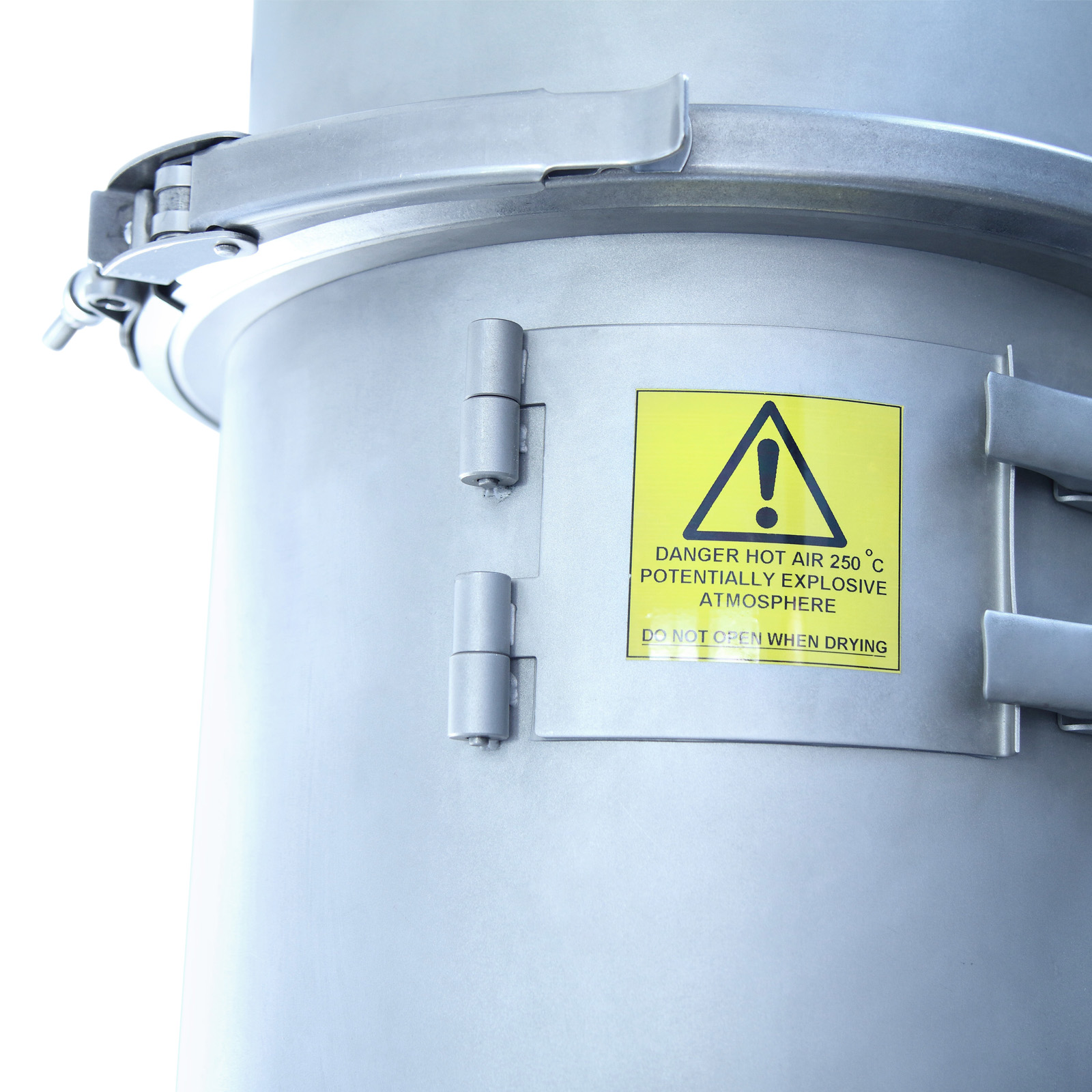
- Drying air temperature up to 250°C
- Maximum flow rate up to 7 l/hr
- Maximum evaporation rate of 3 l/hr
- Tall form chamber straight side to diameter ratio of 3:1, conical discharge section
- Advanced two-fluid nozzle atomisation system
- Supplied with optional nozzle configurations for counter- and co-current atomising
- Individual inlet and exhaust fans with variable-speed control
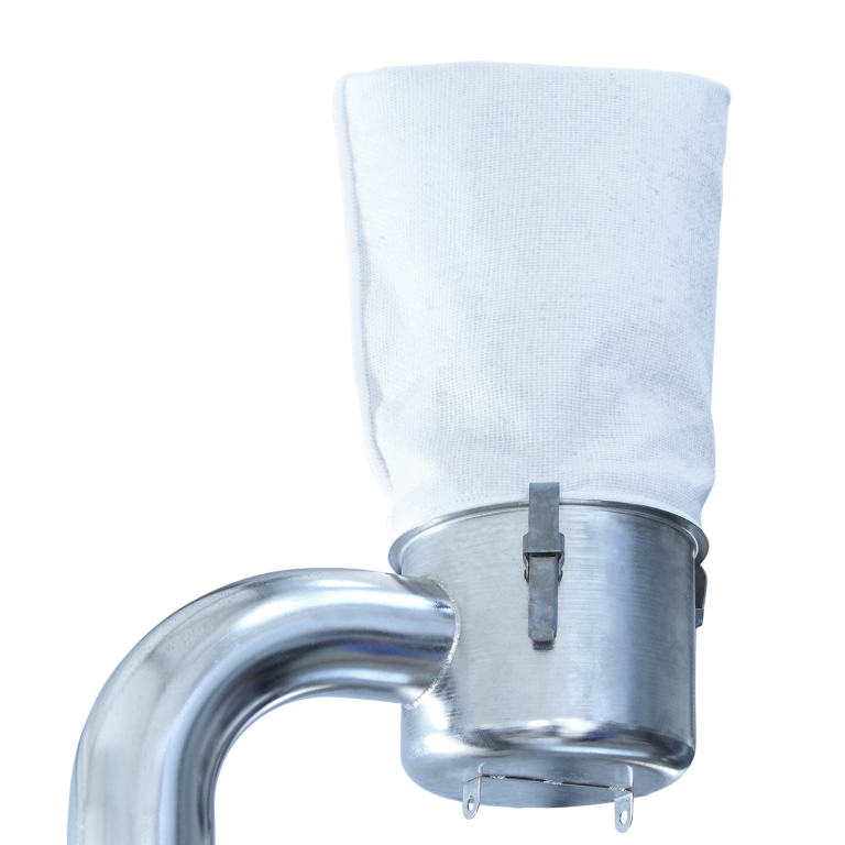
- Bag filter and trace heating options
- Flexible controls and full instrumentation provided in the IP65 control console
- Easily dismantled for inspection and cleaning purposes
- Compact, mobile design
- Data logging facility for all key operating parameters
- Powder discharges from two points, chamber and cyclone
- Low noise levels
- Control and measurement of relative humidity
- Spark arrester on input and enhanced safety extraction fan
Liquid feed: 2-7 l/hr from variable-speed progressive cavity pump
Air flow: Up to 30scfm, using variable-speed fans in ‘push-pull’ configuration
Chamber residence times: Variable up to 9 seconds
Powder collection points: Separate chamber and cyclone discharge points
Atomisation nozzles: 2-fluid type
SPRAY DRYING
Electric air heater: 4.5kW
Drying air temperature: 50-250˚C
Evaporation rates: 1.5-3 l/hr
Typical particle size range: 20-120 microns
SPRAY CHILLING
Air temperature: 2˚C minimum
(Note: not all parameters are necessarily achievable simultaneously)


