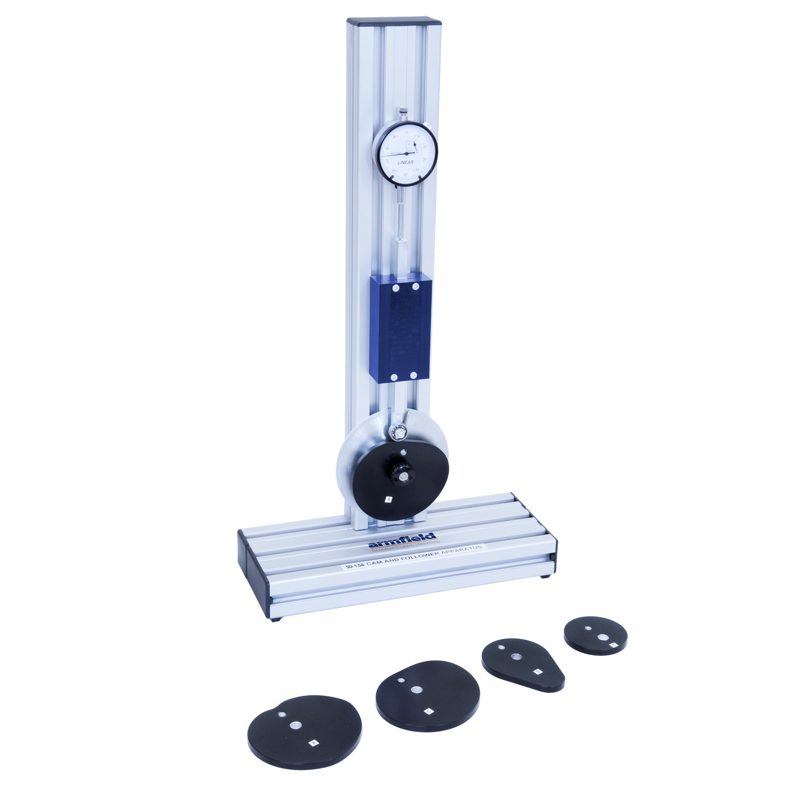
Cam and Follower Apparatus
20 เมษายน 2566
ผู้ชม 390 ผู้ชม
DESCRIPTION
A vertical pillar contains the main spindle for each cam to be rotated, whilst a dial gauge has its anvil resting on the top edge of the cam.
Each cam is mounted on a central shaft and is free to rotate about this shaft. The cams are rotated by hand. The rise and fall displacement of the cam, as it rotates through 360°, is measured using the dial gauge.
The angular position of the cam is shown on a protractor and a pointer. Cams and followers are easily changed and graphs for the variety of cams can be created to compare the linear change with the rise and fall of the follower. A set of cams are supplied as standard along with a set of followers which run on the perimeter of each cam. Each cam can be easily changed and the angular and dial gauge readings are clear.
EXPERIMENTAL CONTENT
- To determine a graph of follower displacement against angular rotation of the cam
- To assess the effect of different cams and followers
- To derive the velocity and acceleration diagrams, and determine the maximum acceleration of the follower
- To compare experimental and calculated results
TECHNICAL SPECIFICATIONS
- Simple harmonic motion cam: Rise/Fall 24mm
- Tangent cam: Large radius 32mm; small radius 15mm
- Eccentric cam: 10mm eccentricity
- Roller follower: Ø19mm
- Dial gauge: 25mm range, 0.01mm resolution
- Angular protractor scale with 360° range and 1° resolution
FEATURES & BENEFITS
- Self-contained bench top unit
- Set of five cams supplied
- Set of two followers supplied
- Angular and linear displacement recorded
- Derive velocity and acceleration diagrams


