Unsteady-State Heat Transfer
20 เมษายน 2566
ผู้ชม 171 ผู้ชม
DESCRIPTION
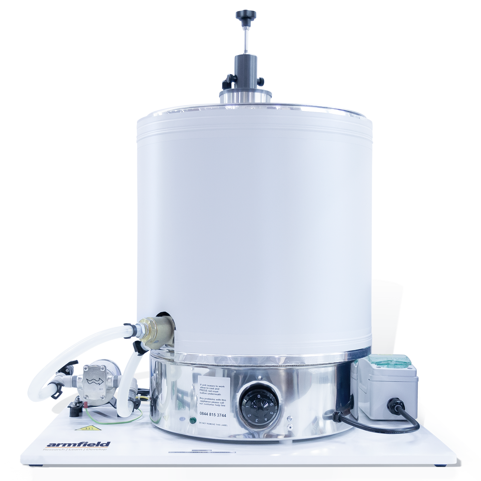
The HT17X equipment consists of a heated water bath together with a set of instrumented shaped test pieces. Each of the shapes incorporates a thermocouple to measure the temperature at the centre of the shape.
A total of six shaped test pieces are provided, i.e. three simple shapes (a rectangular slab, a long solid cylinder and a solid sphere) each manufactured in two different materials (brass and stainless steel).
Measurements taken on a shape in one material can be used to confirm the conductivity of a similar shape constructed from a different material. Transient-temperature/heat-flow charts are supplied for each of the shapes.
A circulating pump mounted alongside the water bath draws water from the bath and returns it at the base of a vertical cylindrical duct, which is located inside the water bath at the centre. A holder ensures each of the shapes is quickly and correctly positioned within the vertical duct for measurements to be taken.
The upward flow of water at constant velocity passing the shape ensures the heat transfer characteristic remains constant and also ensures the water surrounding the shape remains at a constant temperature.
The rate of water recirculation can be varied by using the software to adjust the DC voltage on the pump or use PID controller to achieve flow-rate set-point automatically. The shape holder has been carefully designed to eliminate the need to touch the shape while its temperature stabilises in air, and also to position the shape accurately inside the water bath while transient measurements are taken.
A thermocouple mounted on the shape holder contacts the hot water at the same instant as the solid shape and provides an accurate datum for temperature/time measurements.
A thermostat allows the water to be heated to a predetermined temperature before taking measurements. The large volume of water in the bath ensures that any change in the temperature of the water, as the measurements are taken, is minimal.
The water bath is heated by a mains powered electrical heater, and protected by a residual current device for operator safety. A thermocouple located in the water bath enable the temperature of the water to be monitored and adjusted to the required temperature.
TECHNICAL SPECIFICATIONS
The Armfield ‘Unsteady State Heat Transfer’ accessory HT17X has been designed to allow exercises to be performed in unsteady state heat conduction, when simple solid shapes which are suddenly subjected to convection with a fluid at a constant temperature.
- The water is heated by an electric heating element in the base of the bath having a nominal rating of 3.0 kW
- An adjustable thermostat, at the base of the water heater allows the water to be heated to a predetermined temperature before taking measurements
- Thermocouple at the base of the flow duct, inside the water bath, allows the temperature of the water to be monitored and adjusted to the required temperature
- Comprises of a set of seven solid shapes, manufactured in three simple shapes and two materials. Each sample has a permanently installed K-type thermocouple inside
- The thermocouple mounted on the shape holder contacts the hot water at the same instant as the solid shape and provides an accurate datum for temperature/time measurements
- The resolution of all temperature readings is 0.7°C
- A circulating pump mounted alongside the water bath draws water from the bath and returns it to the base of the vertical cylindrical flow duct
- The accessory is mounted on a PVC baseplate, which is designed to stand on the bench top and connect to the HT10X service unit without the need of tools
- A comprehensive instruction manual is included
FEATURES & BENEFITS
SOFTWARE: A full armBus educational software suite is provided with the HT10X for all the Armfield heat transfer accessories.
Individual experiment interfaces and displayed data types vary to match selected experiment accessories, common examples are listed below:
- Temperatures and other signals such as flow rates, heater voltage and current are displayed on a diagrammatic representation of the equipment
- Control outputs are operated by a control slider or typing in a value between 0 and 100%. Sensor values are read directly in engineering units
- PID automatic control option is available, permitting the temperature set-point to be achieved quickly and precisely, coping with disturbance rejection
- A maintenance screen allows for PID parameter adjustment and thermocouple calibration
- Data from the sensors are logged into a spreadsheet format, with operator control over the sampling intervals (or ‘single-shot’)
- Sophisticated graph-plotting facilities are provided, including plotting of both measured and calculated values
- Graphs update in real-time as the samples are being taken
- Processing of measured values to obtain calculated values is linked to the questions and answers to ensure student understanding
- Experiment data samples are saved, or exported in Microsoft Excel format
- Real-time sensor data is displayed independently from the data logging. It is possible to check the recent history graphical display to inspect the temperature stability prior to taking a sample


