Gear Pump Demonstration Unit
02 มิถุนายน 2566
ผู้ชม 237 ผู้ชม
DESCRIPTION
Two gear wheels operate inside a casing, one is driven while the other rotates in mesh with it. The liquid is carried around in the space between consecutive teeth and then ejected as the teeth mesh. The pump has no valves and it is a positive displacement pump and will deliver against high pressures. The output is a more even flow than that of a reciprocating pump and it is particularly suitable for high-viscosity fluids.
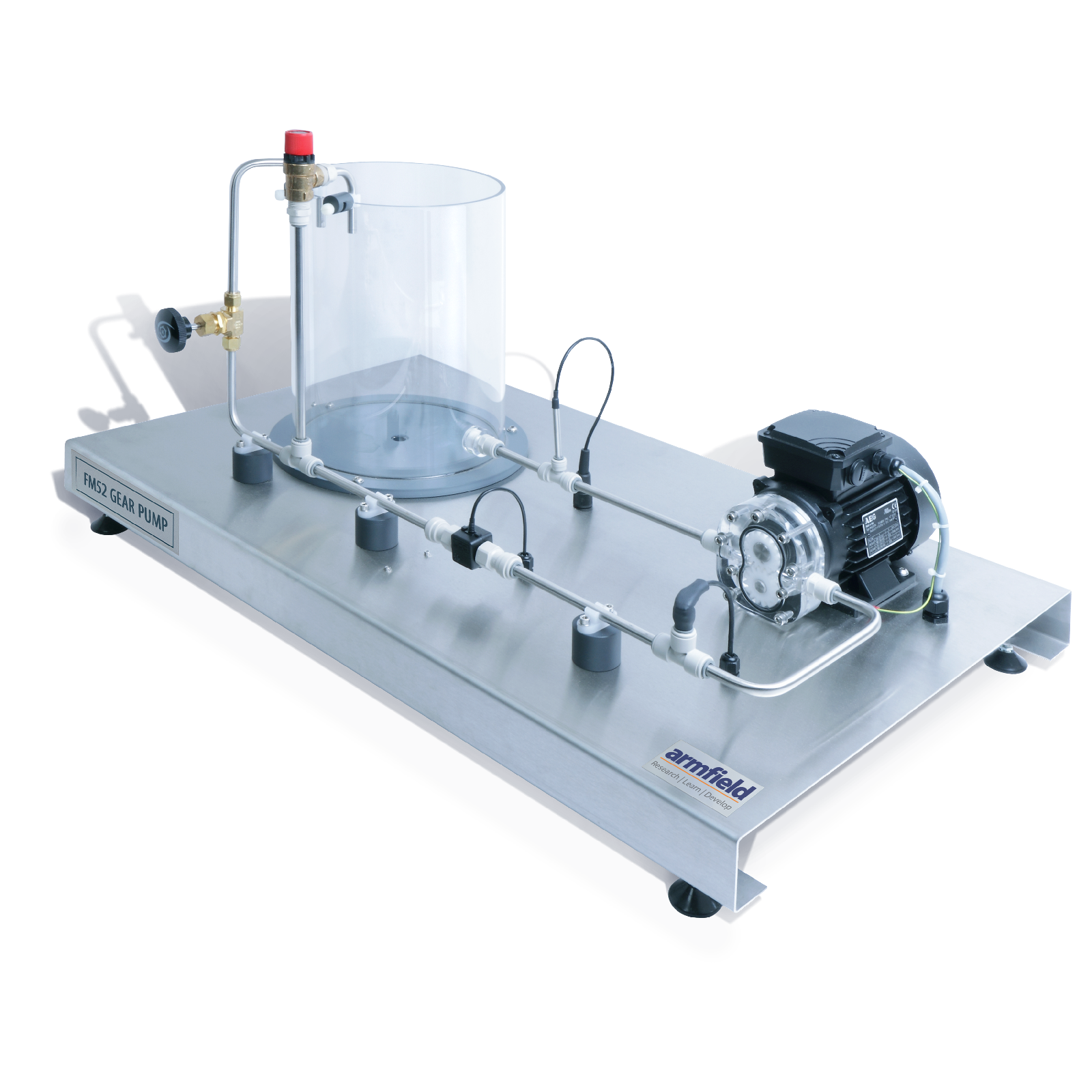
A motor-driven gear pump mounted on a stainless steel plinth with a water reservoir and pipework for continuous circulation. The pump head and the water reservoir are manufactured from clear acrylic for maximum visibility.
A manually operated valve at the pump outlet allows control of the flow and a pressure relief valve protects the operator and the equipment. Electronic sensors measure the pump outlet pressure, the flow rate and the water temperature.
The pump speed is accurately controlled by an advanced electronic inverter within the IFD7 (an essential accessory). This inverter also calculates the torque produced at the motor drive shaft, allowing the power used by the pump to be derived.
The IFD7 also provides the conditioning electronics for the sensors and allows their readings to be displayed on the computer software.
DEMONSTRATION CAPABILITIES
- Demonstration of a gear pump in operation
- Measurement of constant-speed pump performance, including the production of characteristic curves of outlet pressure against:
– Flow rate
– Motor shaft power
– Pump speed
– Pump efficiency
– Volumetric efficiency - Comparison of student calculations with computer results
TECHNICAL SPECIFICATIONS
Max flow rate: 6.5 l/m typical
Max head: 25
Max pump speed: 1,800rpm
Motor power rating: 250W
Gear Diameter: 38mm
Pressure sensor: 0 to 100psi
Pressure Relief Valve: 3bar


