Flow Meter Demonstration
18 เมษายน 2566
ผู้ชม 499 ผู้ชม
DESCRIPTION
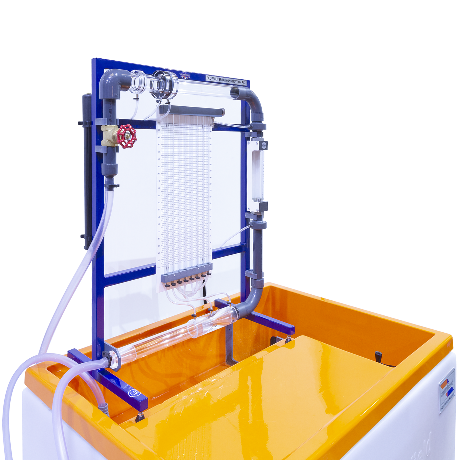
The equipment consists of a Venturi meter, variable area meter and orifice plate, installed in a series configuration to permit direct comparison. A flow control valve permits variation of the flow rate through the circuit. Pressure tappings are incorporated so that the head loss characteristics of each flow meter may be measured. These tappings are connected to an eight-tube manometer bank incorporating a manifold with an air bleed valve.
Pressurisation of the manometers is facilitated by a hand pump. The circuit and manometer are attached to a support framework, which stands on the working top of the Hydraulics Bench. The bench is used as the source of water supply and for volumetrically calibrating each flow meter.
EXPERIMENTAL CONTENT
- To investigate the operation and characteristics of a Venturi meter, variable area meter and orifice plate including accuracy and energy losses
- Comparison of pressure drops across each flow measurement device
- Calibrating each flow meter using the volumetric measuring tank of the bench
- Application of the Bernoulli equation for incompressible fluids
TECHNICAL SPECIFICATIONS
Manometer range: 0-400mm
Number of manometer: tubes 8
Orifice plate diameter: 20mm
Variable area meter: 2-20 l/min
VENTURI DIMENSIONS
Throat diameter: 15mm
Upstream pipe diameter: 31.75mm
Upstream taper: 21° inclusive
Downstream taper: 14° inclusive


