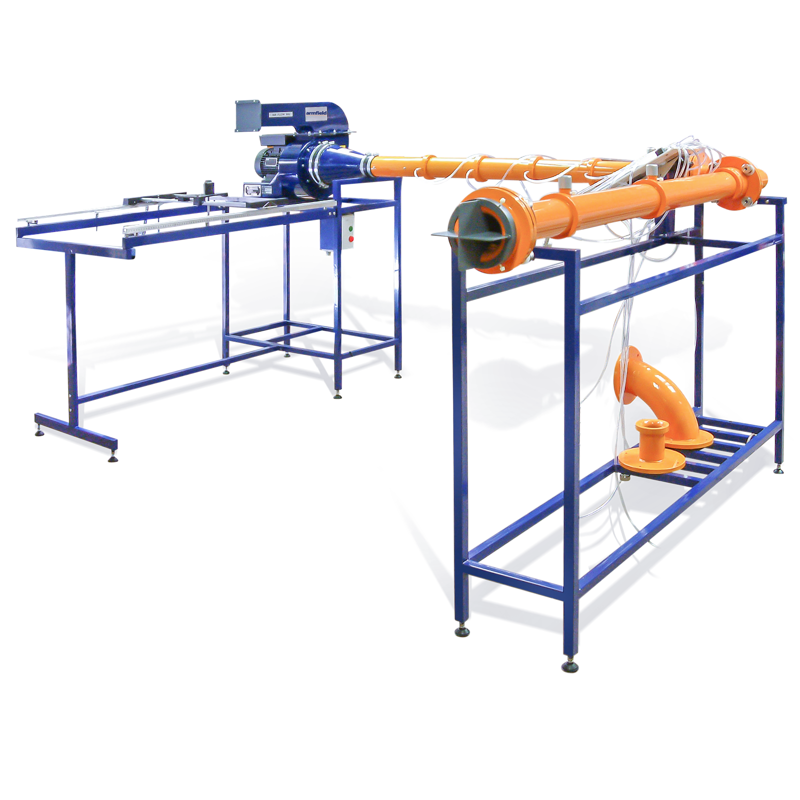
Air Flow Studies
02 มิถุนายน 2566
ผู้ชม 536 ผู้ชม
DESCRIPTION
The equipment comprises a long smooth walled pipe connected to the suction side of an electrically driven centrifugal fan. The fan discharge pipe terminates in a flow control damper for closed conduit work or a plate containing a small aperture for jet dispersion measurements.
Air enters the smooth walled pipe through one of the two flow measurement nozzles provided. Pressure tappings along the length of the pipe permit the pressure gradient to be determined.
A bend or mitred cascade elbow may be fitted midway along the smooth wall pipe for comparison of pressure losses.
Boundary layer growth is determined by the measurement of the velocity profile at five stations along the pipe using a traversing Pitot tube.
A conventional flow measuring orifice plate is supplied for installing in the pipe upstream of the fan for additional demonstrations of pressure loss and recovery. Air-jet studies are carried out on the discharge side of the fan. A Pitot tube is traversed vertically and horizontally at different distances from the discharge orifice to investigate the dispersion properties.
The equipment is mounted on a floor-standing steel frame with an adjacent support for the extended suction pipe. Pressure measurements are made on a multitube inclinable manometer mounted on the support frame.
An electronic manometer bank with data logging software is available as an accessory (order code H14-12).
EDUCATIONAL CONTENT
- Using manometers to measure pressure drop
- Using a pitot-static tube to measure flow
- Dispersion of a jet – to explore the dispersion of a free non-buoyant fluid jet by determining the velocity distribution in the jet at various cross-sections at different distances from the orifice
- Calculating discharge, momentum flux, momentum flux in the jet at each cross-section is investigated
- Boundary layer growth in pipe flow
- Understanding and measuring velocity profiles
- Determine the discharge coefficient experimentally for an orifice plate meter fitted in an air flow pipe
- To determine the pressure distribution along the pipe downstream of an orifice plate
- To determine and compare the pressure drop across the bends and elbows and to examine the static pressure distribution along the downstream pipe
- To compare the performance of the two nozzles as flow meters by checking them against a precalibrated orifice plate meter
TECHNICAL SPECIFICATIONS
- Centrifugal fan capacity: 218 l/s at STP
- Pipe velocity range: 0-35 m/s
- Inlet pipe:
- dia. 80mm
- length 2.75m
- Interchangeable nozzles: dia. 50mm and 80mm
- Internal pipe orifice: dia. 50mm
- Jet discharge pipe orifice: dia. 30mm
- Jet traverse range (downstream LxW): 600 x 140mm
- Manometer range: 0-283mm H2O
- Manometer fluid: Kerosene (s.g. 0.78)


