Computer Controlled Wind Tunnel
26 พฤษภาคม 2566
ผู้ชม 200 ผู้ชม
DESCRIPTION
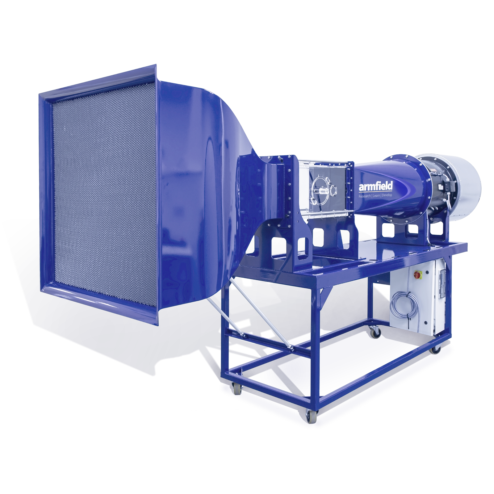
The C30 – Computer Controlled Wind Tunnel enables the user to carry out advanced studies in the Aerodynamics fields including boundary layer experiments, flow visualisation, pressure distribution, study of turbulence and offering the possibility of developing self-design aerodynamics profiles to be tested.
The wind tunnel comprises outstanding features such as computer control, remote operation, datalogging and diagrams plotting in real time.
The system also benefits from clear visualisation of every model under test due to the architecture of the working section in transparent material and the compact design of all components.
TECHNICAL SPECIFICATIONS
-
- A stand-alone computer controlled subsonic wind tunnel for conducting experiments in aerodynamics
- The wind tunnel is mounted on a steel base on wheels for mobility
- Working section of 310mm by 310mm and 600mm long
- The unit operates as an open circuit system
- Inverter controlled AC suction fan to drag the air flow through the working section
- Accurate speed control up to 40m/s
- The duct incorporates a honeycomb flow straightener to even the direction of flow
- The working section incorporates three tappings on its top section to incorporate pitot tubes. These are located at the start of the working section, upstream and downstream of the model under test location
- All the optional and self-built models are inserted through a circular hatch of 160mm diameter. Each of the accessories supplied are built into individual hatches which incorporate an angular scale, enabling the models to be manually rotated to known angles
Linear speed – 0-40m/s
Working section
Length: 600mm
Width: 310mm
Height: 310mmAxial fan power – Approx. 4kW
Fan turning speed – 3000rpm
Measuring ranges
Manometer: 0-250mm H₂0
Wind speed: 0-40m/s
Angle of inclination: +/- 180°
Lift force: +/- 10N
Drag force: +/- 10N
Pitching moment: +/- 3N
EXPERIMENTAL CONTENT
-
Investigation of the development of the boundary layer on a flat plate by measurement of the total head distribution*
C30-11 Manometer Bank / C30-12 Electronic Manometer Bank
- To convert a head measurement using a manometer to an equivalent pressure reading
- To demonstrate the use of a static pressure reading to determine tunnel air velocity
C30-13 Lift and Drag Balance
- To measures the lift and drag forces (aerodynamic loads)
C30-14 Pitot Static Tube
- Static pressure, dynamic pressure and total pressure
- To demonstrate the difference between Static pressure, Dynamic pressure and Total pressure and how Dynamic pressure can be used to determine air velocity
- To show how velocity varies in the test section because of the velocity profile
C30-15 Wake Survey Rake
- Comparison of drag for shapes of equal equatorial diameter
- Visualisation of flow around different body shapes
- Measurement of the wake profile behind different shapes
C30-16 /17-Asoft 3-Component Balance – armSOFT
- To measure lift, drag and moment forces
C30-20 Lift and Drag Aerofoil
- Lift and Drag forces on a symmetrical aerofoil at different angles of attack
- To convert a head measurement using a manometer to an equivalent pressure reading
- To convert head and pressure readings to alternative engineering units
- To demonstrate the use of a static pressure reading to determine tunnel air velocity
C30-22 Drag Models
- Drag forces on bluff and streamlined bodies
- Comparison of drag for shapes of equal equatorial diameter
- Visualisation of flow around different body shapes
- Measurement of the wake profile behind different shapes (requires C30-15)
C30 Airplane Models, C30-35 Car Model
- Visualise airflow over various aircraft at different angles of attack
- Visualise airflow over a car
C30-30-01,02,03,04,06,07 Wing Models
- Lift, Drag and Moment forces on a aircraft wing at different angles of attack
- To convert a head measurement using a manometer to an equivalent pressure reading
- To convert head and pressure readings to alternative engineering units
- To demonstrate the use of a static pressure reading to determine tunnel air velocity
- C30-30-02 Wing Model Type 2 NACA 633-618 (Requires C30-13 or C30-16/17)
C30-31 Aerofoil Model with Flap (Requires C30-13 or C30-16/17)
- Effect of Lift, Drag and Moment forces on a aircraft wing with change of flap angle
- To investigate the effects of control surfaces such as flaps, ailerons, elevator, or rudder
- Influence of a flap
C30-42 Winglets Kit (Requires C30-13 or C30-16/17)
- Wing Theory
- Lift, Drag and Moment forces on a aircraft winglet at different angles of attack
- Observation of eddies on winglets
C30-23 Pressure Cylinder), C30-18-01 Cylinder with Pressure Tapping for 3600 Drive
- Flow around a cylinder
- To investigate the variation in Static Head resulting from a change in cross-section area
- The measurement of pressure distribution around a circular cylinder at different velocities (and Reynolds Number)
C30-21 Pressure Wing NACA 0015, C30-32 Pressure Wing NACA 54118 Profile, C30-33 Pressure Wing NACA 4415 Profile
- Flow and pressure distribution around a symmetrical aerofoil at different angles of attack
- To investigate the pressure distribution across the wake behind the wing
C30-24 Bernoulli Apparatus
- Effect of change in cross-section and application of Bernoulli equation
- To investigate the variation in Static Head resulting from a change in cross-sectional area
- To investigate the Bernoulli equation (if C30-14 Pitot Static Tube is also available)
C30-25 Boundary Layer Plate (requires C30-20 or C30-22)
- Laminar and Turbulent Boundary Layer Development
- To measure the depth of the boundary layer on smooth and rough flat plates
C30-34 Spring Mounted Wing Model
- Aeroelastic Flutter
FEATURES & BENEFITS
- Robust design, manufactured in high quality materials for long life of the product
- Connections to main base unit via flexible hoses and quick release fittings
- The unit is supplied on wheels for ease of movement; these can be removed and the unit bolted to the floor for permanent installation
- Unit supplied with a complete manual including the following sections: Safety, Installation, Equipment Diagrams and Specifications, Routine Maintenance, Operation and Guided Experiments


