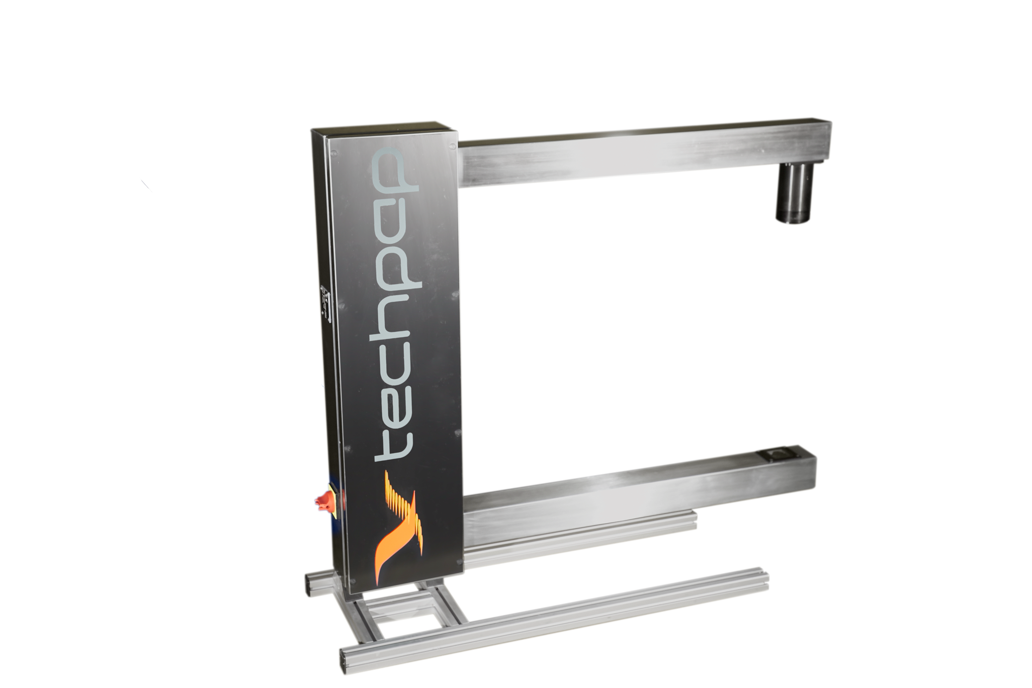
2D F Sensor - On Line paper formation sensor
01 กุมภาพันธ์ 2566
ผู้ชม 173 ผู้ชม
The principle (Paper Formation Tester)
A CCD camera takes images of the moving sheet which is backlit with a LED stroboscope. The images are transmitted to a PC for processing. This PC controls sensor operation and performs the algorithmic analysis. The operator interface gives a continuous image of the sheet, data trend curves, histograms, data arrays, periodic mark information and other relevant paper formation data.
The Measuring Head
The measuring head assembly is a ruggedly built U frame designed to fit from the side of the web. This U frame is composed of a central support to hold the cooling controls and to provide structural support. There are two anodised aluminium tubes attached to the U central structure, the top tube is used for the camera mount and the bottom is used for the strobe mount. This measuring head assembly can be installed on a bracket before the finish reel on the back side of the PM or just in front of a coater with the measuring area about 70 cm from the sheet edge. Emitting and receiving heads are cooled with air and water. An electrical control unit is mounted close to the head assembly and connected to a control computer in the control room.

The Computer
This PC performs the algorithmic treatment of the transmitted images. This algorithmic calculation is the result of 20 years of experience from CTP and Techpap Engineers in the field of formation index development. The Windows OS offers an excellent platform to perform those calculations as well as a user friendly and efficient means to display the output.
By using a 420mA signal or an OPC server, the formation index data can be sent to the DCS or to a data historian on the mill network.


